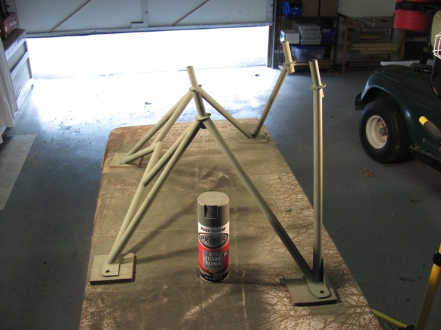
Dec 2, 2013 - Sanded and cleaned the engine mount. Applied primer coat using Rust-Oleum Self Etching primer.
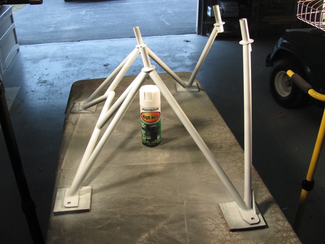
| Dec 2, 2013 - Top coat applied using Rust-Oleum High Heat white paint. |
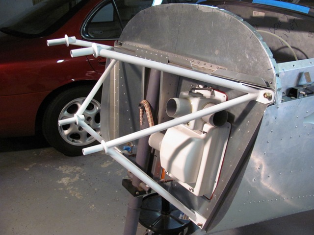
| Dec 2, 2013 - Engine mount temporarily in place. |
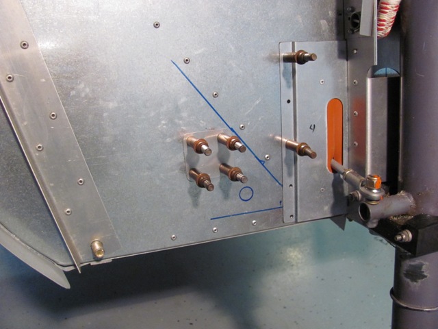
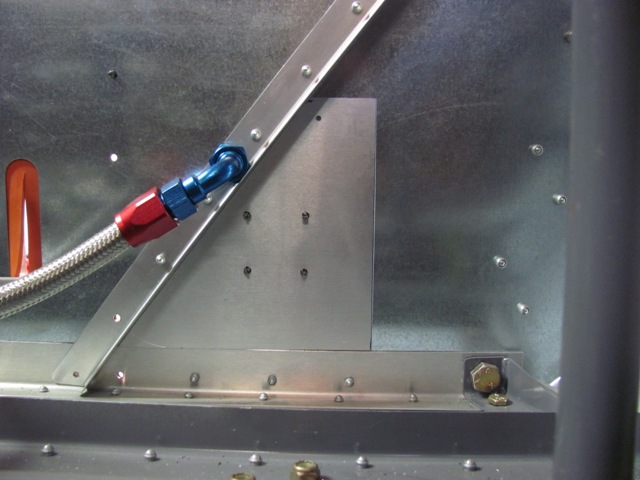
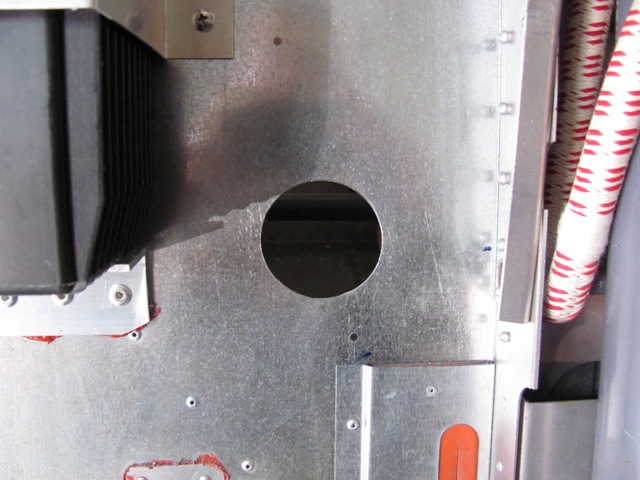
| Mar 8, 2014 - Gascolator firewall pass-through needs to be relocated due to interference with engine mount. |
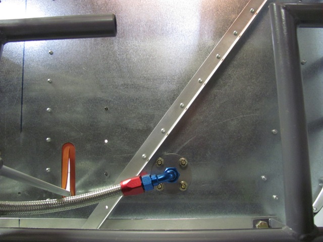
| Mar 8, 2014 - Inside view of existing pass-through location. |
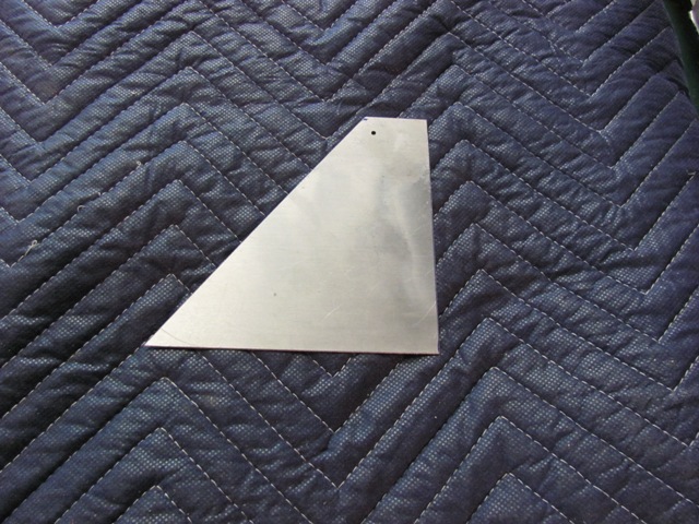
| Mar 8, 2014 - Fabricated .025 inch filler plate for inside of firewall.
This will cover the old pass-through hole, and level surface for new location. |
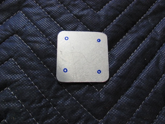
| Mar 8, 2014 - Fabricated engine side cover plate for the old pass-through hole. |
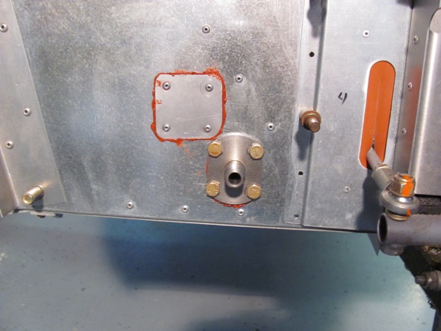
| Mar 9, 2014 - Cover plate covering old gascolator pass-through hole, and location marked for new
hole. |
| Mar 9, 2014 - Inside view showing backing/filler plate covering old pass-through hole, and providing
level surface for new mounting hole. |
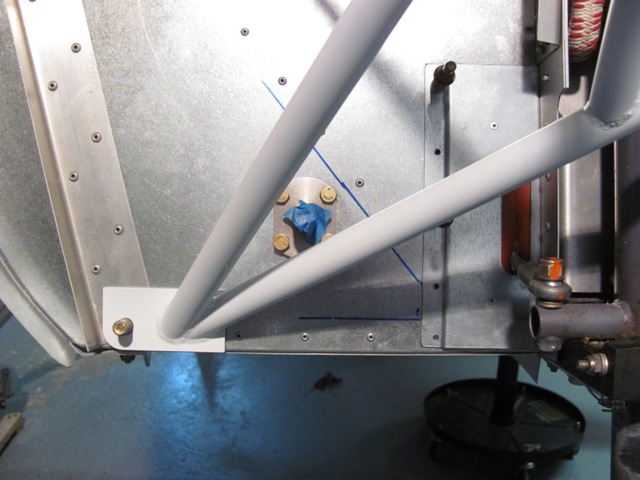
| Mar 9, 2014 - Cover plate riveted in place with seal. Gascolator pass-through reinstalled. |
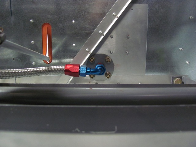
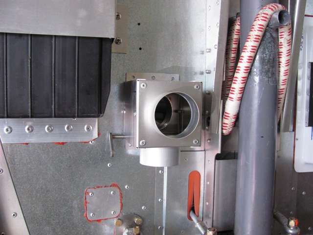
| Mar 9, 2014 - Inside view of new gascolator pass-through location. |
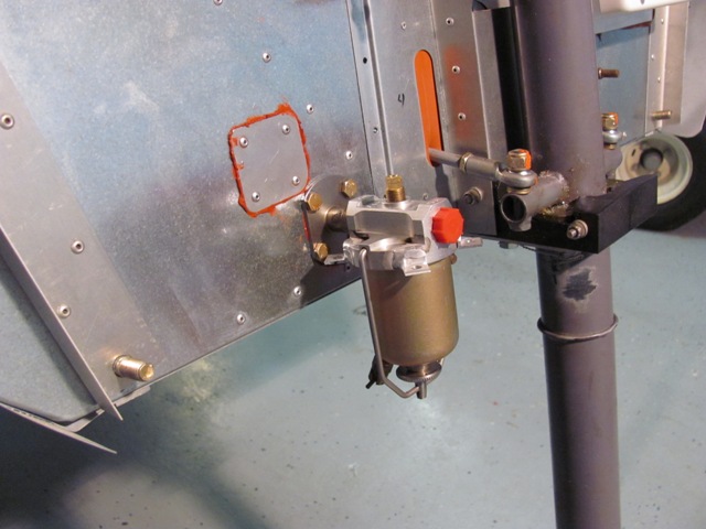
| Mar 9, 2014 - Gascolator installed. |
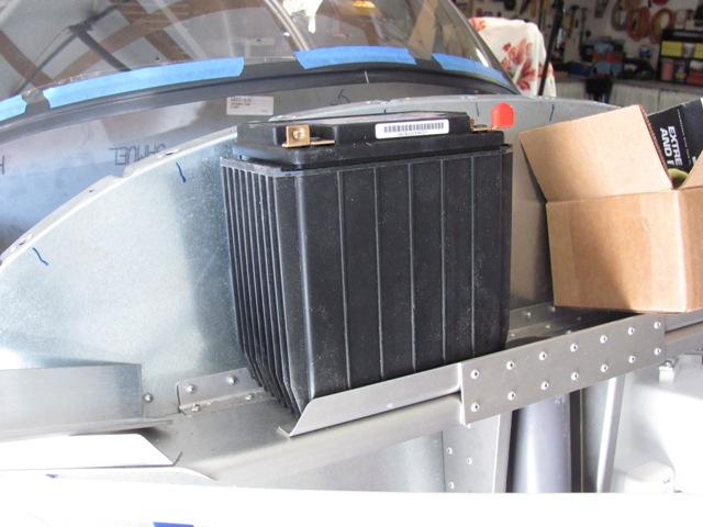
| Mar 21, 2014 - Received the Odyssey PC625 battery, (It does not sit on the shelf.) |
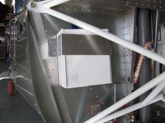
| Mar 21, 2014 - Made a replica of the approximate size of the battery from foam board, Easier to work with when trying to determine proper location. |
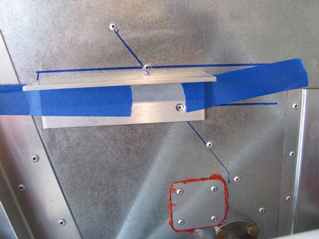
| Apr 11, 2014 - Marked location of battery support on firewall.
Drilled relieve hole in supoort to fit over rivet head. |
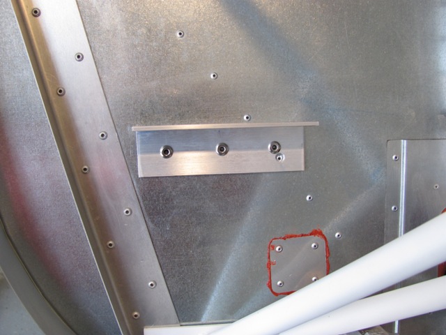
| Apr 11, 2014 - Battery bottom support riveted in placed with 3/16 inch rivets. |
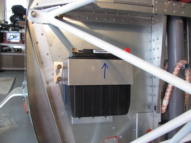
| Apr 11, 2014 - Battery temp mounted. Hold
down bracket will have nut plates and screws for removal when necessary. |
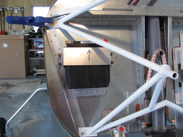
| Apr 18, 2014 - Due to not providing enough room for the cabin heat box, I had to relocate the battery up and
outboard. Fabricated new bottom support. |
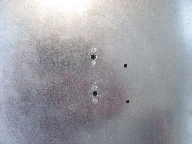
| Apr 18, 2014 - Installed nut plates for hold down
bracket. |
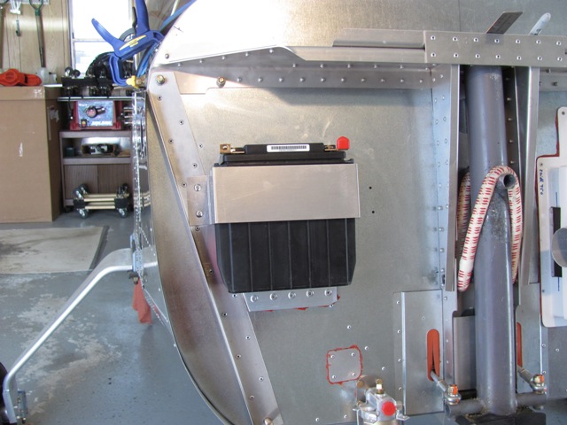
| Apr 18, 2014 - Battery installed. Bracket held
in place with 8-32 screws. Battery can't be placed any higher
due to interference with engine mount. |
| May 5, 2014 - Hole for cabin heat cut. |
| May 5, 2014 - Cabin heat box inserted, but not mounted. |
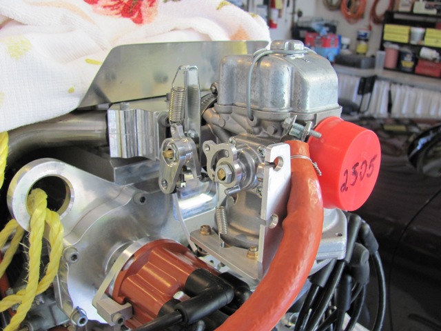
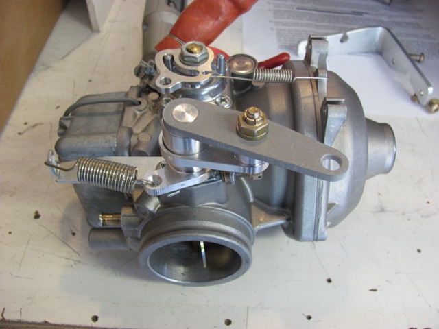
| May 18, 2014 - Carburetor as mounted on inverted engine. |
| May 18, 2014 - Carburetor removed. Short throttle
arm shown in bottom of picture. |
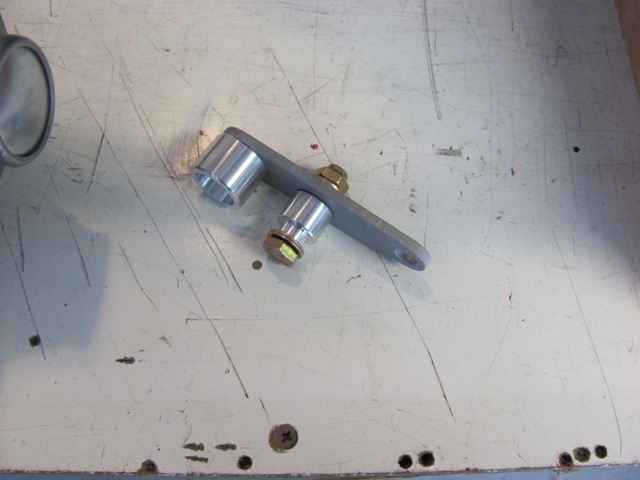
| May 18, 2014 - This is a throttle arm extension to provide a more standard
2-1/2 inch throttle push/pull movement. |
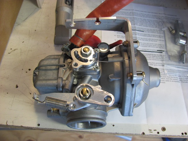
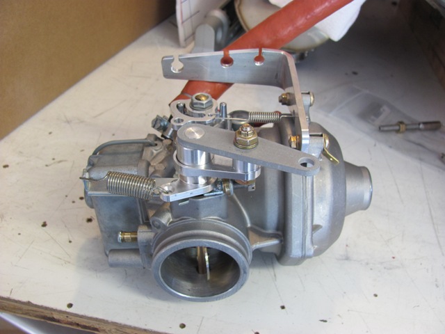
| May 18, 2014 - Throttle arm extension installed. |
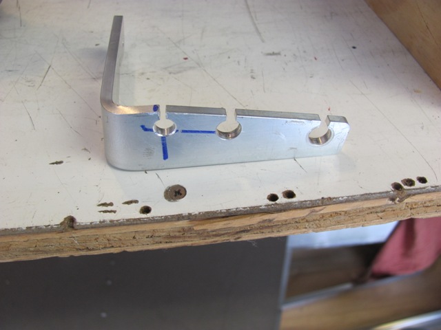
| May 18, 2014 - A new hole needed to be made in the cable attach bracket. |
| May 18, 2014 - The new hole in the bracket provides better alignment of the throttle cable with the throttle
extension. |
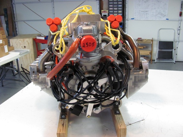
| May 23, 2014 - The engine as taken from the grate. Sitting
inverted, on the wood cradle. |
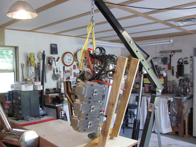
| May 23, 2014 - Raising the engine and rotating into upright position. |
|
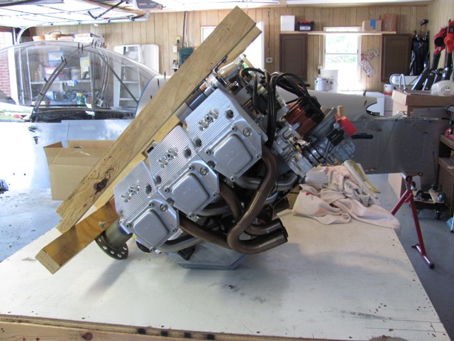
| May 23, 2014 - Engine resting on oil pan and prop flange. |
|
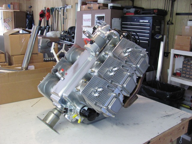
| May 23, 2014 - Wood cradle remove from engine. Another view of engine resting on oil pan. This is extremely sturdy and fully capable of supporting the weight. |
|
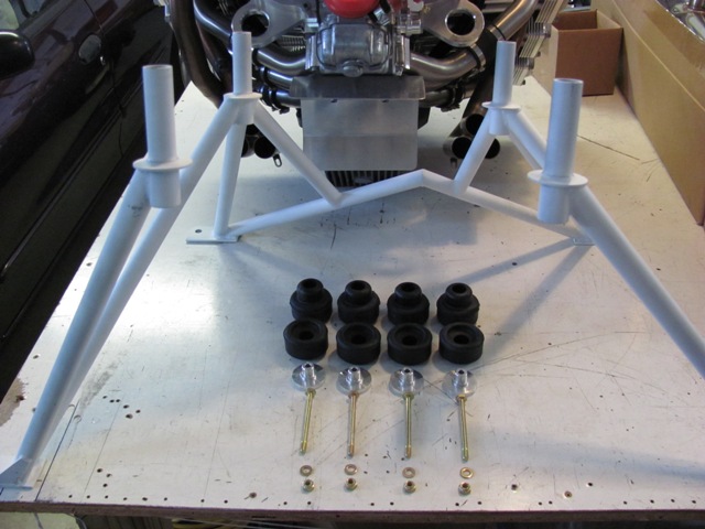
| Jun 1, 2014 - Engine mount, male & female bushings, engine side washers, AN4-31A bolts, washers, & nuts. |
| Jun 1, 2014 - Male on the bottom, female on top. |
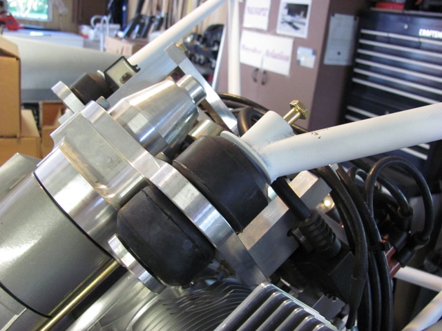
| Jun 1, 2014 - Top left with female bushing on mount side and male on the engine side.
Bolt will recess into the mount and through the washer. |
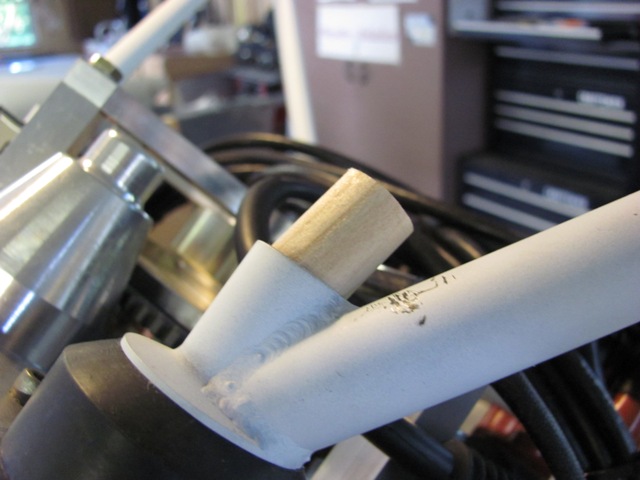
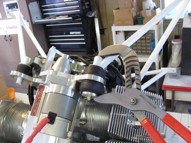
| Jun 1, 2014 - A short piece of 5/8 inch round dowel was used hold the bolt in place while compressing the bushings. |
| Jun 1, 2014 - With the wood dowel inside the mount hold the bolt, the bushings were compressed enough to get
the small washer and nut started. |
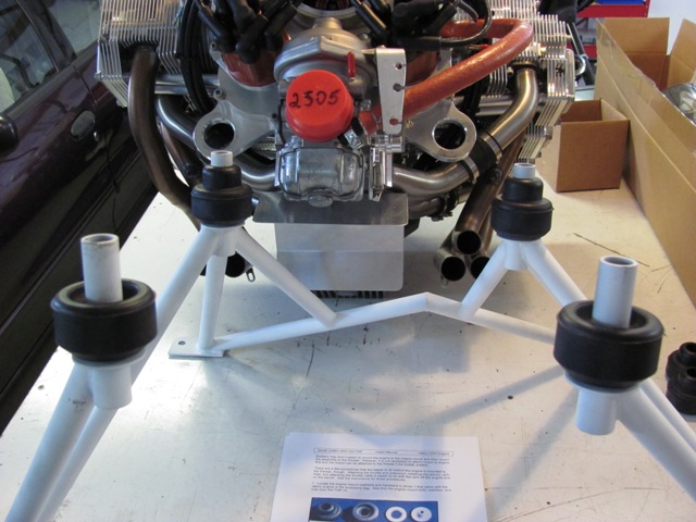
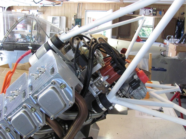
| Jun 1, 2014 - The mount installed. The bottom
mounts were extremely difficult, barely able to be done with two people, one with small fingers. |
Back to HOME>>
Back to TOP>>
|