|
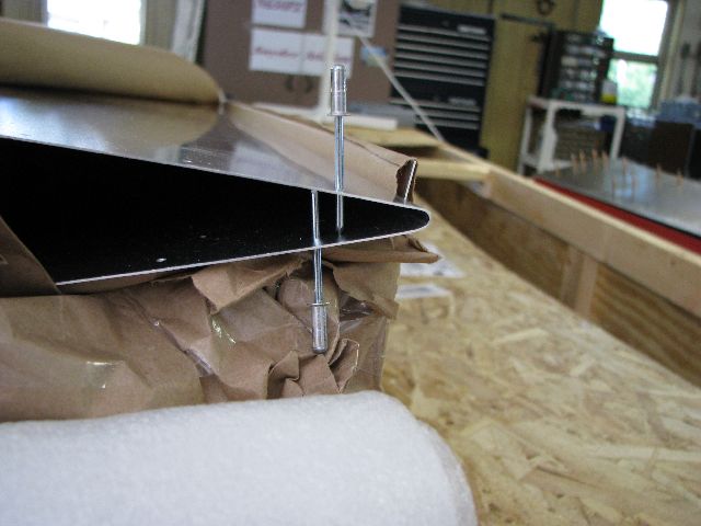
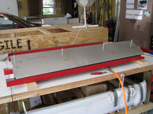 Aug 29, 2009 - Starting to build ailerons, Note small block of wood (on right side of photo) under the out-board
trailing edge. This creates a built-in twist to the aileron for aerodynamic qualities.
|
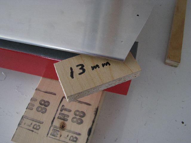 Aug 29, 2009 - Closer look at the block used to twist the aileron. This is done for both sides. |
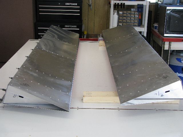
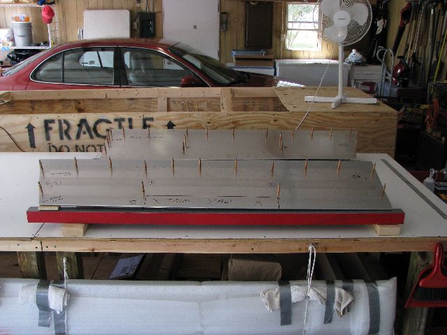 Aug 29, 2009 - Both ailerons assembled with clecos prior to riveting.
|
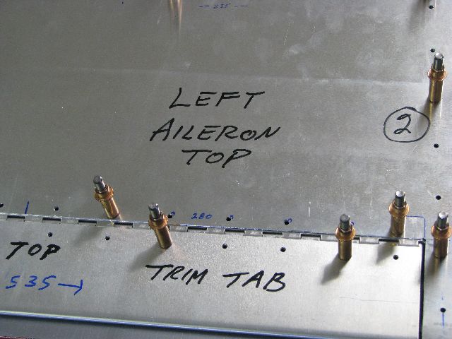
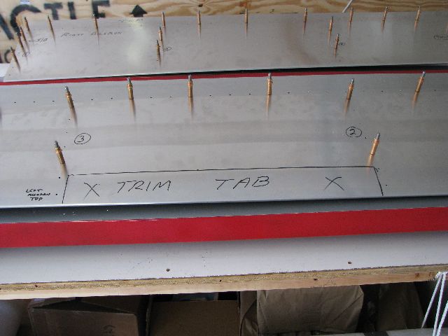 Aug 29, 2009 - Marked location for electric trim tab. |
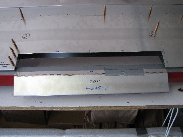 Sep 2, 2009 - Cut out portion of aileron trailing edge for insertion of trim tab. |
 Sep 2, 2009 - Trim tab positioned, and hinge temporarily attached. |
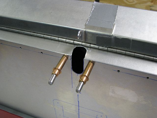 Sep 7, 2009 - Cut out for trim tab servo rod to penetrate the lower skin and support channel. |
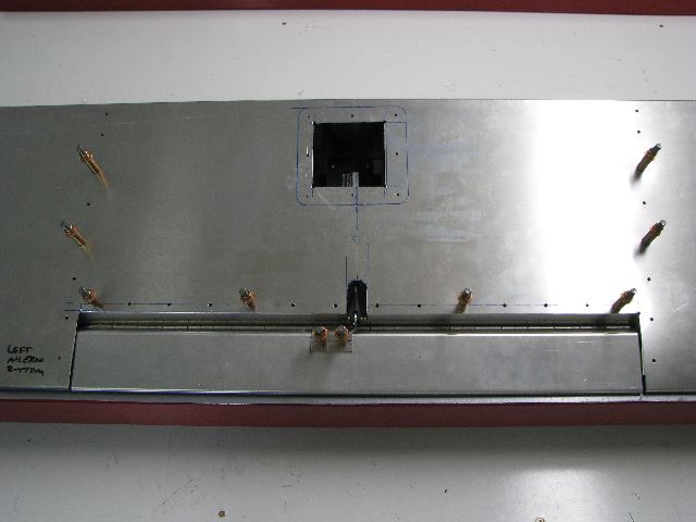 Sep 11, 2009 - Tested, installed, and adjusted the trim tab servo (looking through bottom skin). |
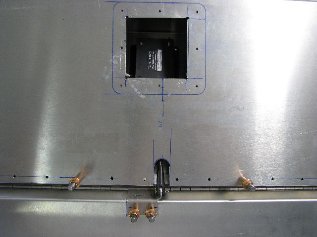 Sep 11, 2009 - Closer look at servo unit, connecting rod and control horn on trim tab.
|
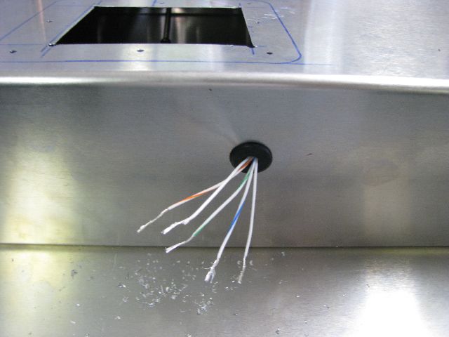 Servo wiring through front of aileron, eventually leading to cockpit.
|
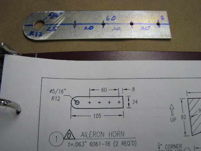 Sep 11, 2009 - Fabricated aileron horn used to move the ailerons in flight. |
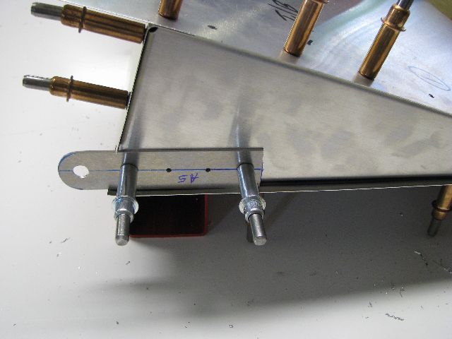 Sep 11, 2009 - Aileron horn in position on bottom front edge. |
 Sep 11, 2009 - After exchanging a few emails with Zenith Aircraft regarding the trailing edge rivet problems (see above),
Zenith sent me replacement flaps for free.
|
 Sep 11, 2009 - I checked the training edge rivet line, and found that the pre-drilled rivet holes were now correctly
aligned.
|
 Sep 16, 2009 - Replacement flaps rebuilt and riveted. Ready for attachment to main wing when completed. |
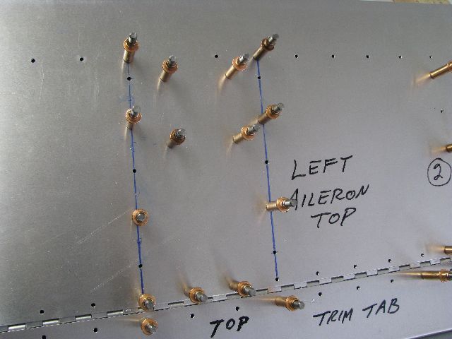 Sep 22, 2009 - I decided to add a couple of stiffeners under the top aileron skin to help support the trim tab servo
unit. The blue lines indicate where the stiffeners are located.
|
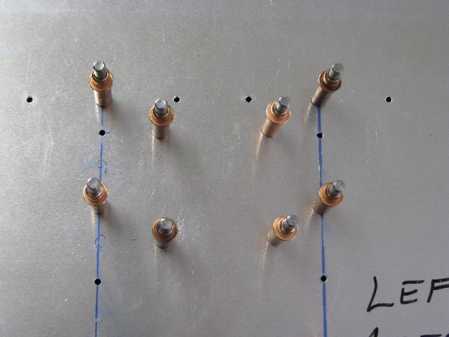 Sep 22, 2009 - A closer look. The four clecos in the center hold the servo unit. I am not riveting the ailerons
at this time, awaiting final word from Zenith about possible modifications.
|
To be continued |
|
Enter supporting content here |